Cockpit
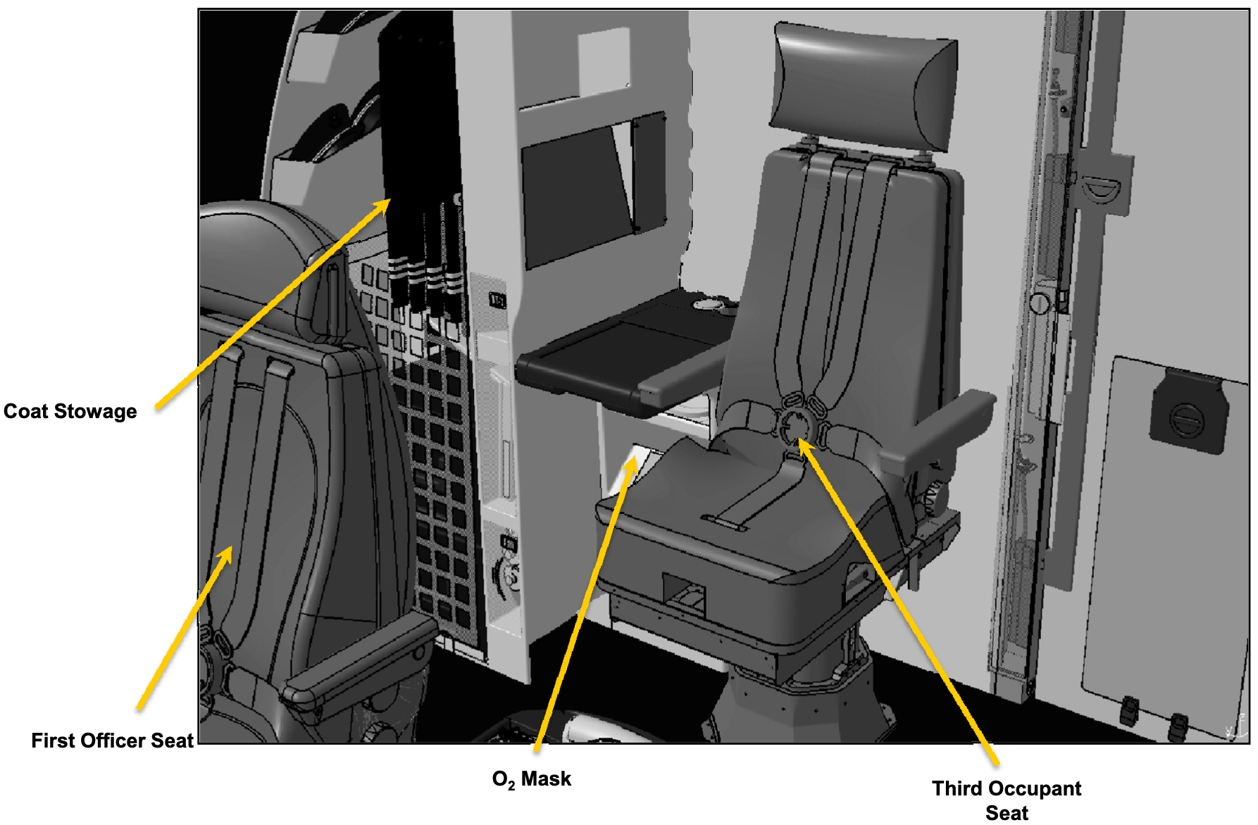
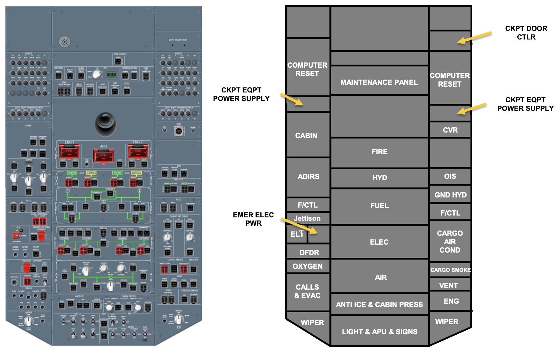
A flight deck implies a bigger space with room to move or walk around. As opposed to a cockpit, with just enough space for seats that pilots might climb into. Starting at the back wall of the flight deck, there are hat clips and the pilot’s wardrobe closet. On the other side there’s a jump seat that slides and folds out, there’s a crash axe nearby, as well as a flashlight oxygen cylinder and portable breathing equipment. Detailed circuit breaker panels are situated near the back wall on both sides.
Cockpit includes:
- Instrument panels:
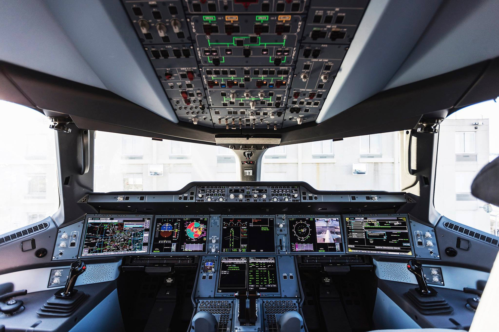
- Overhead panel
- Main instrument panel
- Glareshield
- Pedestal
- The captain and first officer lateral consoles that each have:
- One sidestick
- One steering handwheel
- One oxygen mask
- One stowed laptop
Seating
The pilot and co-pilot seats move back into the side for entry. They have a five point harness and ample adjustments for proper access to flight controls as well as comfort. There are heated foot mats in the floor. Eye level locators between the front windshields indicate proper seat position, ensuring optimal visibility for all flight deck operations.
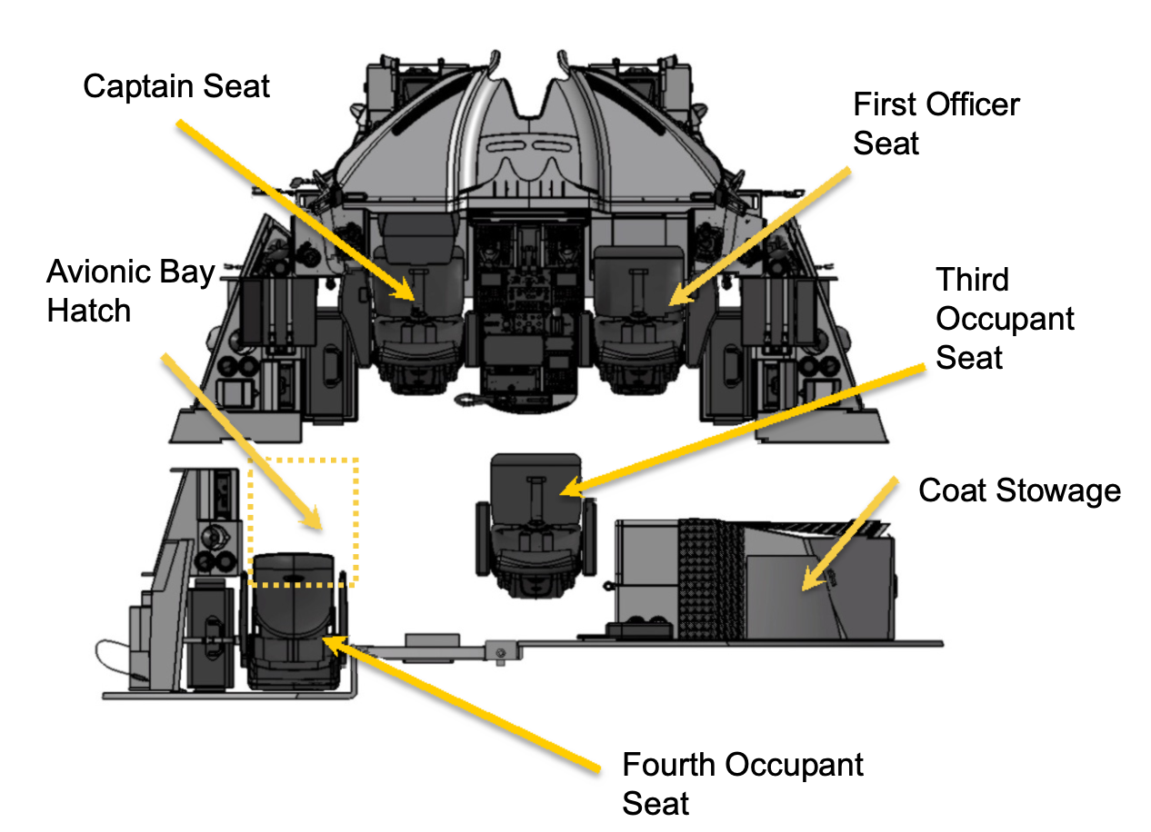
The ideal position is reached when the white sphere is completely hidden behind the front red sphere as viewed by the person adjusting the seat the armrest on the outside of each seat has tilt and vertical adjustment knobs for unobstructed arm mobility when using the side stick or tiller there’s a small step near the inside shoulder of each seat back for access to an overhead escape hatch. A compartment holds an emergency rope that flight deck crew can use to slide down the side of the plane.
Side Stick
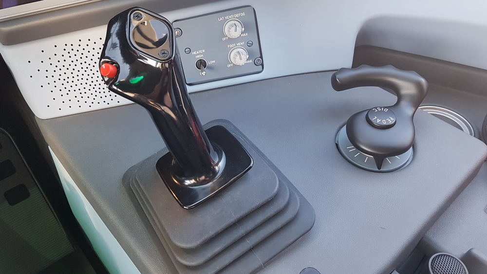
A side stick controller on each side gives the pilot or co-pilot control over the roll and pitch of the aircraft an autopilot priority switch disconnects autopilot if it’s engaged with autopilot off holding the button gives this side stick priority a pitch trim switch can set the auto trim rate for the horizontal stabilizer or allow manual trim adjustment in direct mode. There’s a switch at the front of the stick for radio or intercom communication.
Steering
While taxiing under 30 knots, a steering tiller can be used to turn the nose landing gear up to 80 degrees in either direction. In order to avoid damage to the nose landing gear, rotation is limited from 80 degrees down to 9 degrees max as speed increases from 30 to 100 knots and above.
Rudder pedals can be used at any time to rotate the nose landing gear but are limited to the maximum 9 degrees.
- In the past the flight bag at each seating position held airplane specific operation manuals navigation charts checklists and so on. Electronic tablet devices have replaced most of these items in recent years.
- Some airplanes may also have a head-up display allowing the pilot or co-pilot to view relevant real-time information like runway alignment airspeed altitude and more.
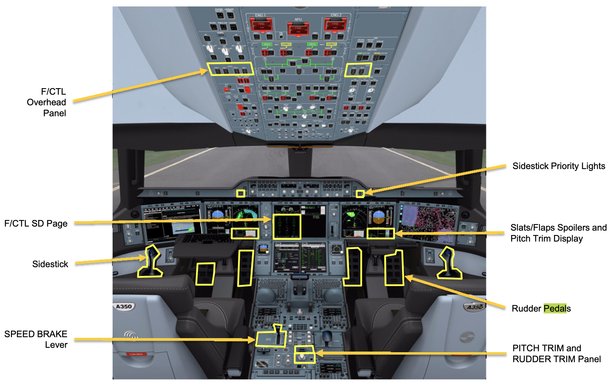
Rudder Pedals
With feet in the lower position rudder pedals move forward and back for rudder control. Moving feet to the upper position allows pedals to rotate engaging left and right main landing gear breaks. A mechanical linkage ensures the pedals on both sides move together. Pilots can adjust the pedal position with a knob at the front.
Control Panels
Control panels starting with the overhead panel. Many of the switches in these panels have lights that convey important info something like the warning lights in a car’s dashboard. However unlike simple car warning lights when pilots interact with these switches their lighting status can update.
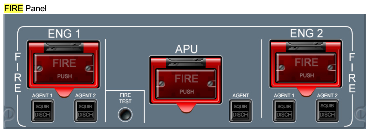
A fire module sits in the center the switches glow red when a fire is detected some of these switches are protected with doors that must be flipped open for access pressing a fire switch helps mitigate fire spread and damage by shutting off fuel to the respective engine and arming fire extinguisher bottles among other things once armed nearby switches discharge specific fire extinguishing bottles when pressed.
The outboard module starting at the back the entrance knob and dome switch control flight deck lighting the protected aural warn switch allows the audible warning system to be silenced if there’s an issue with the oral system. This system handles the many warning sounds and phrases that alert pilots to critical events. Window heat and probe heat toggle the icing functionality for windows and external temperature measuring devices or probes primary flight control computers can be individually disabled using any of these three protected switches.
The CVR section handles the cockpit voice recorder which records not only sounds inside the flight deck but also all connected audio channels both internal and external.
The next panel section has knobs to control lighting brightness for circuit breaker panels. Overhead panels the compass and more turning this knob to the storm setting illuminates the complete flight deck all panels and dome lights to maximum intensity.
The next panel controls communication during plane servicing with the service intercom switch on all flight deck and service intercom channels are opened the call button sounds a horn in the external service panel area at the end of this module there are captain’s side reading light and windshield wiper controls.
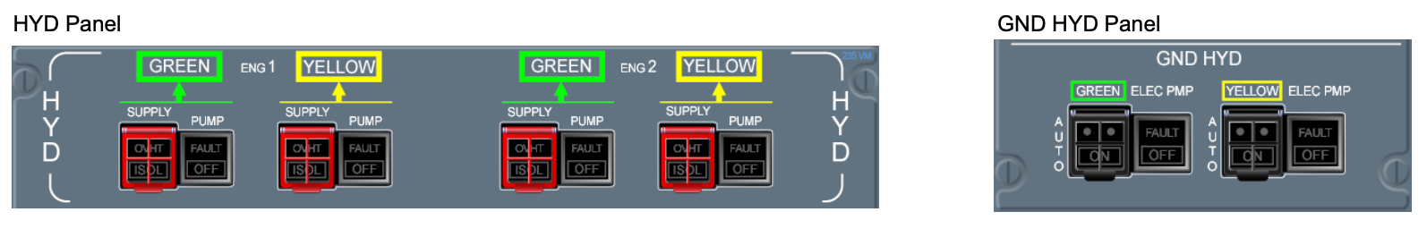
The HYDraulic section has controls for various hydraulic system scenarios since there are three separate hydraulic systems in the plane for safety and redundancy this panel allows various configurations so these systems can work as normal or supplement each other in varying conditions the electrical section has a knob for various electrical system scenarios for example the ess setting powers only essential systems the guarded switch next to this knob turns off power to select cabin systems which can be useful for isolating sources of smoke in the cabin whether from electrical arcing or some other source the guarded rat switch allows flight crew to manually deploy the ram air turbine or rat under normal conditions the rat will deploy automatically if power is lost in flight.
Battery knobs control on board battery, packs one and two the left and right gen switches toggle engine driven electrical power generators, each has a protected disconnect switch to disconnect the generator shaft from the engine. If for example leaving a malfunctioning generator connected could lead to engine damage.
The APU switch can disconnect the auxiliary power unit from the system in case of an electrical fault the ext switch allows crew to toggle the external power connection. The APU pull turn switch functions something like a car ignition the start setting is held for 3 seconds to start the APU once started the switch reverts to the run position the APU fail light illuminates for any electrical fire or starting issues the terrain awareness and warning system has protected switches to turn off aural warnings associated with landing gear terrain detection and flaps.
The GS switch turns off oral warnings related to glide slope which is the pre-calculated path of descent in the flight control system.
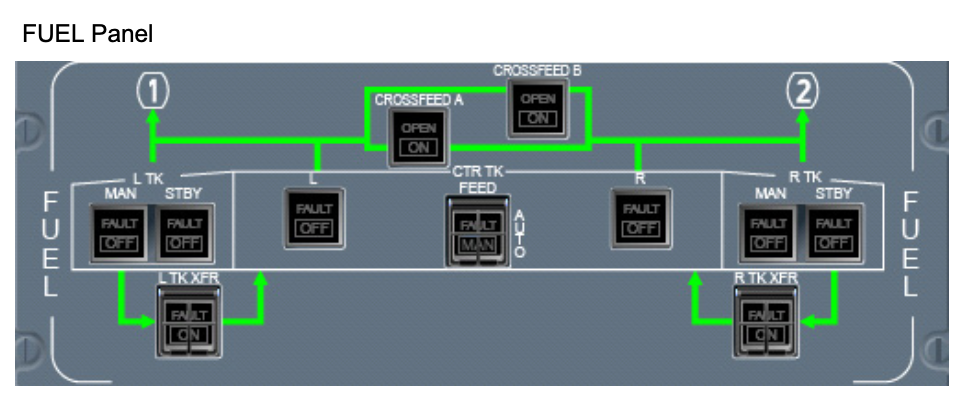
The Fuel subsection with the manual transfer switch in off mode the fuel system functions as normal the other settings allow flight crew to select specific fuel tank configurations. Left and right boost pump switches control supplemental electrically powered fuel pumps,where the system under normal operation relies on engine driven pumps as the primary source of fuel pressure. The gravity transfer switch opens valves so that the fuel can move between tanks by gravity alone. The air section has climate controls at the top, and also ventilation settings for cargo compartments.
The trim air switch toggles valves that allow air from the engine bleed air system into the climate control system. When the PAC flow switch is active the air conditioning units or packs enter high flow mode which can be useful for clearing smoke or odors. There’s a switch for recirculating air fans the guarded ram air switch can open external ports at low altitude for flight deck or cabin ventilation.
Left and right pack switches grant manual control over air conditioning packs which otherwise operate automatically based on desired climate control settings, cross bleed left and right bleed switches grant manual control for engine bleed air valves and APU bleed air. The anti-ice section controls de-icing capabilities in the left and right engine cowling and wings.
The ELT or emergency locator transmitter pull turn knob can test and arm the ELT. The cargo section handles fire reporting and deploying fire extinguishing bottles in the cargo areas. Equipment cooling refers to cooling systems for equipment bays. The inlet switch controls cooling fans and an external valve to take in outside air. There’s also a switch for exhaust air produced by the equipment cooling system in the pressurization section. There’s a guarded switch for emergency depressurization of passenger and flight crew areas. The auto press switch allows manual pressurization control, which is usually an automated process.
In manual mode the dial beneath sets the pressurization rate. The guarded ditching switch activates a ditching sequence. Ditching is a controlled emergency water landing in an aircraft not designed for such. The ditching sequence closes all valves below the aircraft flotation line, except for the ram air valve. The PAX OXY switch deploys passenger oxygen masks.
There’s a switch to toggle the evacuation horn and a pull turn switch for evacuation lighting, beyond that we see the co-pilot side windshield wiper and reading light switches.
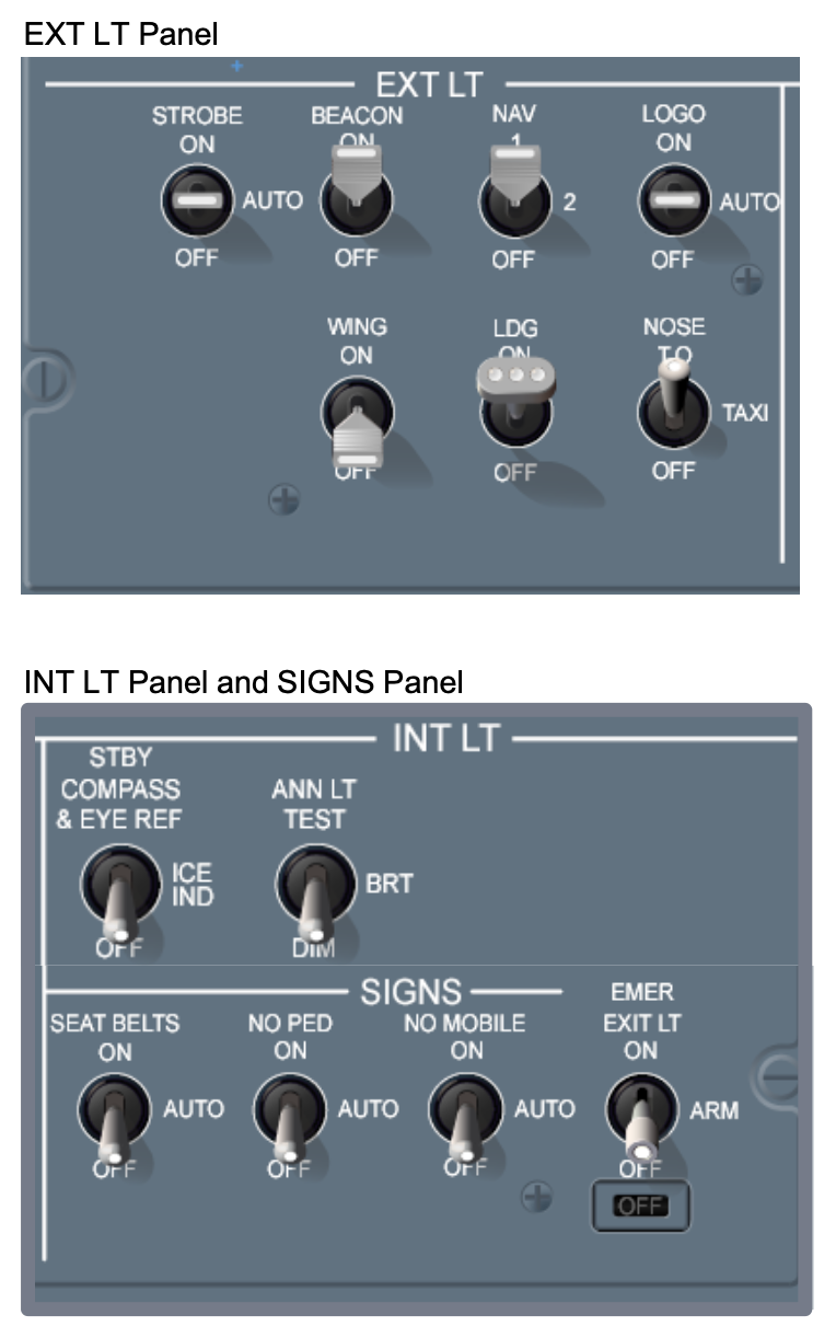
Lights Overhead Module
Starting from the pilot side there are external lighting control switches for navigation, beacon, strobe and logo lights. The landing lights section has a taxi light switch and special switches with triple LED indicators for left, right and nose landing gear lights. A pair of switches in the PAX light section control the seat belt and no personal electronic devices warning signs in the passenger cabin.
Glare Shield
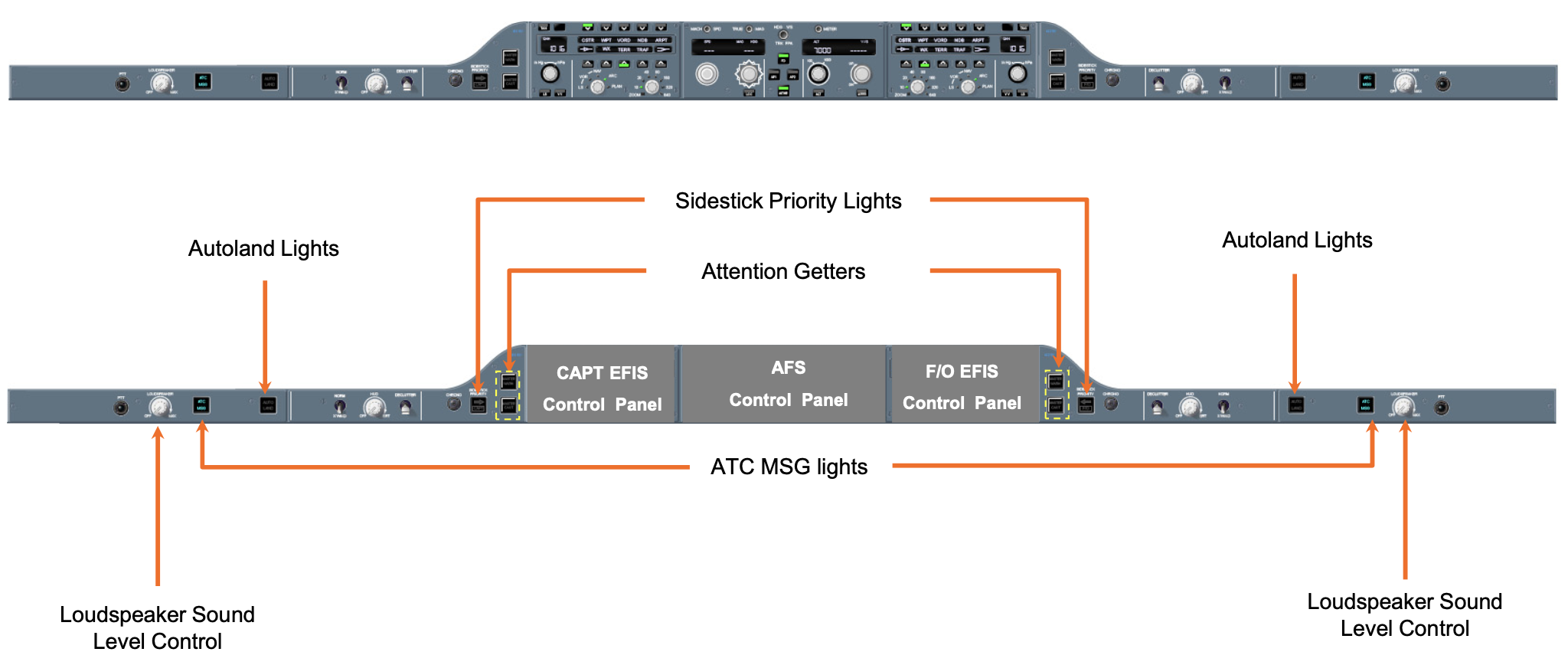
The glare shield control layout is mostly symmetrical side to side. Starting at the captain’s side the two left-most styles control brightness for main displays one and two beneath.
The CHRONO button controls a basic stopwatch type function, which can be displayed on the primary flight display. The warning caution master switch shows a red warning or yellow caution alert, if either are triggered. The switch must be pressed to acknowledge the alert and rearm the system for any further alerts. Pressing the side stick button gives priority to the pilot’s side stick and deactivates autopilot, and aural priority left message sounds. The next cluster of buttons is a non-verbal system to supplement pilot’s communication with air traffic control. There are options to accept stand by reject or load pre-programmed messages into the flight control system, which can then be quickly accessed in communicating with air traffic control.
Radio and Control Tuning Section
It has knobs and buttons to quickly change displays for relevant info and a radio panel with many related functions. The left and right buttons correspond to the left and right sides of main display number two beneath. The map button displays the last selected map type of which there are various options. An adjacent knob adjusts map range.
The FMS button displays flight management system details like position flight plan performance route and more. The CNS button opens screens related to communication navigation and surveillance capabilities afforded by the many special antennas and systems on the craft. The CHKL button opens the electronic checklist. SYN opens synoptic pages, which are simplified real-time diagrams of critical systems showing for example the status of the hydraulic or fuel system and major components at a glance. DATA displays the last selected data page which can be items like important documents or aeronautical charts. Terrain, traffic alert and weather switches bring up overlays corresponding to those systems the barrow switch changes how barometric pressure is displayed.
The small screen has surrounding buttons for quick access to features that affect how items are displayed on primary screens below, including weather radar navigation details and so on.
The TUNE/MENU button and dial are also for navigating settings and menus on this screen ident broadcasts aircraft identification to air traffic control for 18 seconds.
Flight Control Panel
It sits at the center of the glare shield and is used to input and monitor flight data in the automatic flight control system. The FD switch displays pitch and roll commands from the flight guidance system on the primary displays. The SPD switch selects between various ways of measuring air speed and how that info appears on nearby flight control displays. The HDG button displays heading on the flight control display. The dial tunes to the desired heading which is an angular measurement from north at 0 degrees clockwise to 359 degrees.
NAV selects between various available ways of measuring lateral or side to side movement as the aircraft travels its flight path. The APPR button selects between various approach systems, where airplanes and airports have different available equipment setups.
Aircraft can choose to rely on their own data for airport approach, or some blended procedure where airports have systems in place to relay precision guide information to the craft. The half bank switch limits bank angle in a turn especially at higher speeds. To avoid uncomfortable g-forces on passengers and crew, and to mitigate the likelihood of a stall.
Switches in the center of the flight control panel deal with autopilot and related functionality.
The AP switch toggles autopilot at toggles auto throttle capability. The XFR or transfer switch determines data channels and sensors used for the flight director system. The guarded EDM switch activates emergency descent mode, and is not in fact a special guarded switch to play electronic dance music for impromptu sky raves.
On the copilot side an flc switch determines how flight level change is maintained. Pilots generally select to maintain horizontal air speed for climbs but vertical air speed for descents. The ALT inner dial sets the desired altitude and the outer dial, sets measurement in feet or meters the alt switch holds the aircraft at its current altitude.
The V-NAV, VS and FPA switches are different modes to auto-calculate pitch commands. V-NAV uses data for the flight plan, VS uses desired vertical speed to generate pitch commands which the crew can set using the nearby dial the fpa switch uses a desired flight path angle which can also be set with the dial.
Main Instrument Panel
Large interchangeable screens can be customized to show things like flight parameters, navigation and communications info. Approach and weather charts synoptic pages for critical systems and component status electronic checklists maintenance data and more. A small integrated standby instrument in the center can supply necessary info to fly on emergency power with no other available displays. It has nearby buttons and a dial for customization.
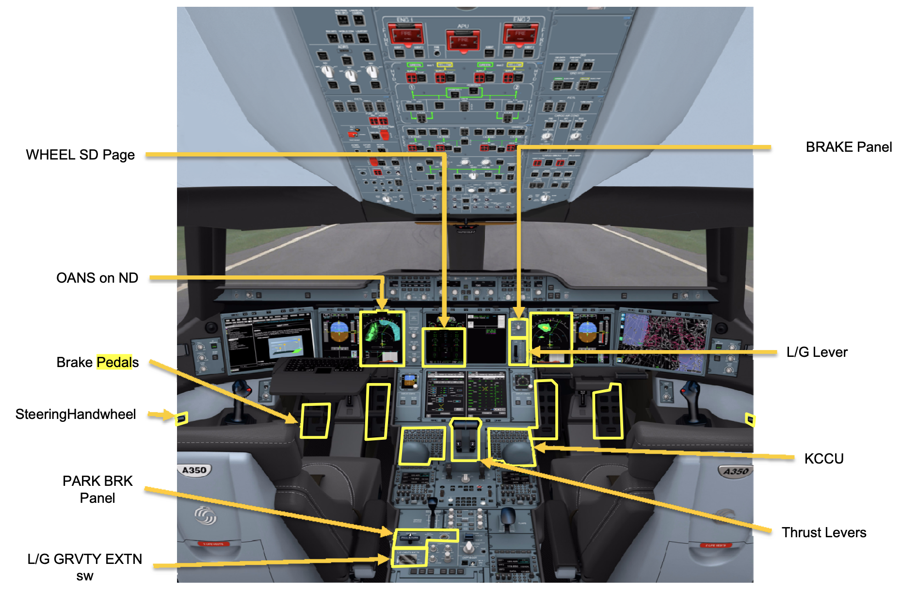
Landing Gear and Brakes
The landing gear lever extends or retracts landing gear, and must be pulled out to operate. In the event of a malfunction, the guarded alternate gear release switch electronically disengages up locks, so landing gear can naturally free-fall to the down and locked position.
The guarded gear aural switch mutes the gear aura warning. The auto brake switch has settings to maintain a constant deceleration during landing. The RTO setting controls braking for a rejected takeoff scenario, where the plane has to stop on the runway instead of taking off. The protected alternate brake switch grants full manual brake control without automated braking assists. The NOSE STEER switch toggles nose wheel steering capability.
Center Pedestal
The center pedestal is situated between both pilot seats and houses various systems input devices and controls for throttle and flight control surfaces. Starting towards the front of the plane, there’s a keyboard for interacting with the flight management system and display screens. The buttons along the top are connected to the flight management system as well. The message button displays relevant system alerts route opens the pre-programmed flight route. The direct-to-dialog button offers a streamlined way of changing or adding waypoints to the flight plan. The departure arrival button shows the respective flight plan info depending on the phase of flight.
Beneath the keyboard there are more buttons for flight system access. MAP shows a map and flight plan overlay. FMS opens flight management system settings, CNS shows a communications and navigation screen. The CHKL button shows relevant checklists, SYN brings up synoptic pages. DATA can show charts, video, docs and database info. CAS can show or hide messages from the engine indicating and crew alert system or ICAS.
This system monitors many critical engine processes. The CNCL and EXEC buttons in the top right can approve or cancel flight plan modifications. The trek style mouse and surrounding buttons and knobs provide robust interaction with the flight management system and display units. There are buttons to select which display to interact with a stacked knob for scrolling through lists and settings, and push to talk buttons at either side of the palm rest to open communication through selected transmit channels.
Audio Control Panel
It handles the many available radio communication channels. CALL buttons along the top let the crew select which antenna to use for broadcast. Very high frequency antennas are best for line of sight communications and can be blocked by buildings or mountains. High frequency antennas can penetrate some obstacles but are prone to distortion from atmospheric conditions like solar flares geomagnetic storms and so on.
SAT com is the satellite communication channel that may be ideal in places with limited VHF and HF equipment. CAB opens communication between pilots and flight attendants in the cabin. Volume switches pop up to activate respective listening channels. Pilots can listen on any number of channels. The PTT and INT rocker switch selects between external communication and internal channels reserved for communication between pilots or to ground crew. The next three dials let pilots listen in on various radio beacon and guidance systems that transmit info to the aircraft. Many of these channels transmit in morse code.
ID is a constant three-letter broadcast. Voice allows voice transmissions through this channel. NAV, one, two and three are channels related to flight management systems, and usually transmit audio for specific airport identification among other things. DME is the distance measuring equipment channel, MKR is the marker beacon channel, which aircraft can use to determine distance from a selected beacon, usually located along runways. PA is the public broadcast channel that lets crew broadcast to passengers in the cabin.
Trim Control Panel
It has a split aileron trim switch that’s spring loaded to the center position for adjusting aileron trim the surrounding lwd and rwd labels stand for left wing down and right wing down respectively the rudder trim switch is also spring-loaded and the surrounding labels indicate nose left or nose right.
Reversion Switch Panel
It ensures critical info will appear on displays especially in the event of a primary flight display failure the display switch has three set scenarios to quickly switch certain digital info panels to particular displays based on which displays are still available the inhibit switch disables display tuning customization the flight director and auto throttle alternate source switch changes which channel this data uses from multiple available channels again for redundancy the left and right cursor inhibit switches disable the respective trackball and buttons left and right primary flight displays control respective display screens.
ISI is the small display in the center the ads switches let crew cycle through info from various sources in the air data system like air temperature probes angle of attack sensors and so on irs switches cycle data from internal reference units these units have accelerometers and laser gyros to measure things like aircraft altitude and heading among others.
The park brake pull turn switch sets the parking brake. At the back of the center pedestal, there’s an interphone that can be used to communicate with passengers or other flight crew. An onboard paper printer is situated behind a thin slot in front of the interphone with its associated buttons. Pilots may print out things like weather information, clearances from air traffic control and performance numbers for takeoff multi-function spoilers can be extended with the flight spoiler lever in direct mode though like other systems spoilers often function automatically as directed by the flight control system.
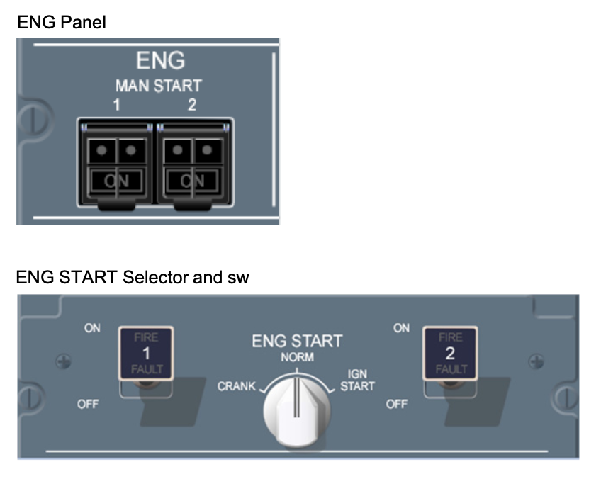
The slat flap lever has a release handle on top to advance past gated positions 2 and 4. There’s also a protected deploy switch to override the system and force deploy slats and flaps to position 3. The engine panel has a switch for continuous ignition this setting is generally automated but can be manually toggled by crew. Continuous ignition guards against engine flameout due to various events like heavy weather or turbulence.
The start switch in auto mode lets the engine start sequence be directed by automated systems. Left or right crank lets the crew dry crank the engine or crank engines as part of a manual start sequence. There are fire indicator lights for left and right engines. The pilot event switch when pressed in marks flight data recorder info for future maintenance investigation.
Throttle Quadrant Assembly
Switches at the base of the throttle quadrant assembly initiate the left or right engine start sequence. Throttle levers for each engine reach maximum throttle as they move forwards. Finger pull levers on the front of each throttle lever allow rearward travel into the thrust reverser section. A button on the side of each lever toggles auto throttle on or off.
TOGA (Take Off or Go Around) switches at the side toggle takeoff or go around modes. Takeoff mode increases throttle for takeoff based on automated flight plan data. Go around mode is an alternate automated throttle process to maintain flight. For example, in an aborted landing scenario: the co-pilot side has some of the same modules as the pilot side with the addition of a lighting panel and the cockpit door panel. The stacked display knobs control brightness for various displays.
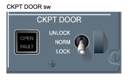
The integral stacked knob controls lighting brightness for many panels in the flight deck with its outer ring and glare shield panel brightness with the inner knob. The flood switch controls instrument panel flood lights. In the cockpit door panel, left and right buttons toggle display for surveillance cameras on the other side of the door. The unlock button unlocks the door. There’s a keypad, just outside the flight deck door with an emergency code that crew members may use to force unlock the door after a time delay. During the time delay the red switch on this panel can deny the emergency open request.
KCCU
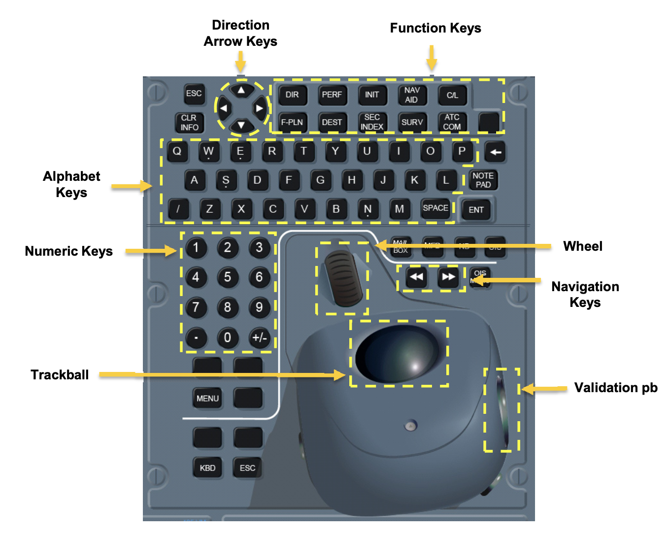
The cockpit has two Keyboard and Cursor Control Units (KCCUs). Both are on the center pedestal.
The KCCUs enable the flight crew to directly interact withthe onside ND, MFD, OIS and the mailbox section of the SD. Each KCCU displays a different cursor. In addition, the KCCU can also interact with the offside MFD.
The KCCU has two interfaces:
- A keyboard (KBD)
- A cursor control device (CCD).
In normal operation the CCD enables the control of the cursor via the trackball of the CCD and the KBD enables. In case of failure of CCD or KBD, the remaining available interface is able to perform both needs thanks to specific backup.