Antennas are widely used in the field of telecommunications and we know many applications for them. Antennas receive an electromagnetic wave and convert it to an electric signal, or receive an electric signal and radiate it as an electromagnetic wave.
Yagi Uda antenna
In the past, dipole antennas were used for TV reception.
Reflector elements (usually only one is used) are slightly longer than the driven dipole and placed behind the driven element, opposite the direction of intended transmission. Directors, on the other hand, are a little shorter and placed in front of the driven element in the intended direction. hese parasitic elements are typically off-tuned short-circuited dipole elements, that is, instead of a break at the feedpoint (like the driven element) a solid rod is used. They receive and reradiate the radio waves from the driven element but in a different phase determined by their exact lengths. Their effect is to modify the driven element’s radiation pattern. The waves from the multiple elements superpose and interfere to enhance radiation in a single direction, increasing the antenna’s gain in that direction.
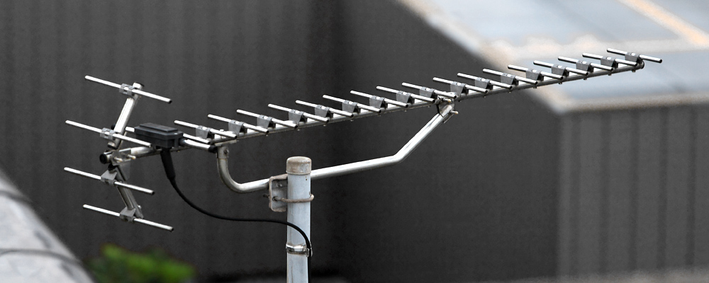
Also called a beam antenna and parasitic array, the Yagi is very widely used as a directional antenna on the HF, VHF and UHF bands. It has moderate to high gain of up to 20 dBi, depending on the number of elements used, and a front-to-back ratio of up to 20 dB. It radiates linearly polarized radio waves, and can be mounted for either horizontal or vertical polarization. It is relatively lightweight, inexpensive and simple to construct. The bandwidth of a Yagi antenna, the frequency range over which it maintains its gain and feedpoint impedance, is narrow, just a few percent of the center frequency, decreasing for models with higher gain, making it ideal for fixed-frequency applications. The largest and best-known use is as rooftop terrestrial television antennas, but it is also used for point-to-point fixed communication links, in radar antennas, and for long distance shortwave communication by shortwave broadcasting stations and radio amateurs.
Satellite dish antenna
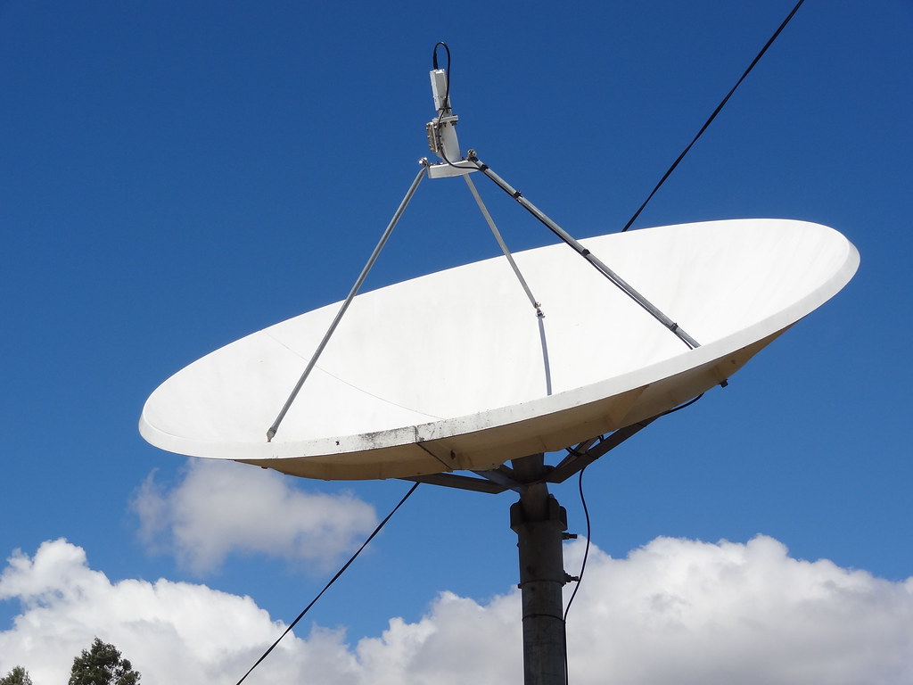
Nowadays we have moved to dish TV antennas. These consist of two main components, a parabolic shaped reflector and a low noise block down converter.
A satellite dish is a dish-shaped type of parabolic antenna designed to receive or transmit information by radio waves to or from a communication satellite. The term most commonly means a dish which receives direct-broadcast satellite television from a direct broadcast satellite in geostationary orbit.
Microstrip antenna or Patch antenna
The cellphone in your hand uses a completely different type of antenna, called a patch antenna. These types of antennas are inexpensive and fabricated easily onto a printed circuit board. A patch antenna consists of a metallic patch or strip placed on a ground plane with a piece of dielectric material in-between. Here, the metallic patch acts as a radiating element. The length of the metal patch should be half of the wavelength for proper transmission and reception.
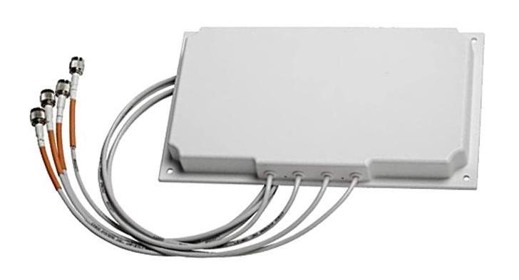
A patch antenna is a type of antenna with a low profile, which can be mounted on a surface. It consists of a planar rectangular, circular, triangular, or any geometrical sheet or “patch” of metal, mounted over a larger sheet of metal called a ground plane. They are the original type of microstrip antenna described by Howell in 1972; the two metal sheets together form a resonant piece of microstrip transmission line with a length of approximately one-half wavelength of the radio waves. The radiation mechanism arises from fringing fields along the radiating edges. The radiation at the edges causes the antenna to act slightly larger electrically than its physical dimensions, so in order for the antenna to be resonant, a length of microstrip transmission line slightly shorter than one-half the wavelength at the frequency is used. The patch antenna is mainly practical at microwave frequencies, at which wavelengths are short enough that the patches are conveniently small. It is widely used in portable wireless devices because of the ease of fabricating it on printed circuit boards. Multiple patch antennas on the same substrate called microstrip antennas, can be used to make high gain array antennas, and phased arrays in which the beam can be electronically steered.
A variant of the patch antenna commonly used in mobile phones is the shorted patch antenna, or planar inverted-F antenna (PIFA). In this antenna, one corner of the patch (or sometimes one edge) is grounded with a ground pin. This variant has better matching than the standard patch. Another variant of patch antenna with the partially etched ground plane, also known as printed monopole antenna, is a very versatile antenna for dual-band operations.
Antennas receive an electromagnetic wave and convert it to an electric signal, or receive an electric signal and radiate it as an electromagnetic wave. We have an electric signal, so how do we convert it to an electromagnetic wave? You might have a simple answer in your mind. That is to use a closed conductor and with the help of the principle of electromagnetic induction, you will be able to produce a fluctuating magnetic field and an electric field around it. However, this fluctuating field around the source is of no use in transmitting signals. The electromagnetic field here does not propagate, instead, it just fluctuates around the source.
In an antenna, the electromagnetic waves need to be separated from the source and they should propagate. Before looking at how an antenna is made, let’s understand the physics behind the wave separation. Consider one positive and one negative charge placed a distance apart. This arrangement is known as a dipole, and they obviously produce an electric field as shown. Now, assume that these charges are oscillating as shown, at the midpoint of their path, the velocity will be at the maximum and at the ends of their paths the velocity will be zero. The charged particles undergo continuous acceleration and deceleration due to this velocity variation. The challenge now is to find out how the electric field varies due to this movement.
Let’s concentrate on only one electric field line. The wavefront formed at time zero expands and is deformed as shown after one eighth of a time period. This is surprising. You might’ve expected a simple electric field as shown at this location. Why has the electric field stretched and formed a field like this? This is because the accelerating or decelerating charges produce an electric field with some memory effects. The old electric field does not easily adjust to the new condition. We need to spend some time to understand this memory effect of the electric field or kink generation of accelerating or decelerating charges.
We will discuss this interesting topic in more detail in a separate video. If we continue our analysis in the same manner, we can see that at one quarter of a time period, the wavefront ends meet at a single point. After this, the separation and propagation of the Wavefront happens. Please note that this varying electric field will automatically generate a varying magnetic field perpendicular to it. If you draw electric field intensity variation with the distance, you can see that the wave propagation is sinusoidal in nature. It is interesting to note that the wavelength of the propagation so produced is exactly double that of the length of the dipole. We will come back to this point later. This is exactly what we need in an antenna. In short, we can make an antenna if we can make an arrangement for oscillating the positive and negative charges.
In practice, the production of such an oscillating charge, is very easy. Take a conducting rod with a bend in its center, and apply a voltage signal at the center. Assume this is the signal you have applied, a time-varying voltage signal. Consider the case at time zero. Due to the effect of the voltage, the electrons will be displaced from the right of the dipole and will be accumulated on the left. This means the other end which has lost electrons automatically becomes positively charged. This arrangement has created the same effect as the previous dipole charge case, that is positive and negative charges at the end of a wire. With the variation of voltage with time, the positive and negative charges will shuttle to and fro.
The simple dipole antenna also produces the same phenomenon we saw in the previous section and wave propagation occurs. We have now seen how the antenna works as a transmitter. The frequency of the transmitted signal will be the same as the frequency of the applied voltage signal. Since the propagation travels at the speed of light, we can easily calculate the wavelength of the propagation. For perfect transmission, the length of the antenna should be half of the wavelength. The operation of the antenna is reversible and it can work as a receiver if a propagating electromagnetic field hits it.
Let’s see this phenomenon in detail. Take the same antenna again and apply an electric field. At this instant, the electrons will accumulate at one end of the rod. This is the same as an electric dipole. As the applied electric field varies, the positive and negative charges accumulate at the other ends. The varying charge accumulation means a varying electric voltage signal is produced at the center of the antenna. This voltage signal is the output when the antenna works as a receiver. The frequency of the output voltage signal is the same as the frequency of the receiving EM wave. It is clear from the electric field configuration that for perfect reception, the size of the antenna should be half of the wavelength. In all these discussions, we have seen that the antenna is an open circuit.
Now let’s see a few practical antennas and how they work. In the past, dipole antennas were used for TV reception. The colored bar acts as a dipole and receives the signal. A reflector and director are also needed in this kind of antenna to focus the signal on the dipole. This complete structure is known as a Yagi-Uda antenna. The dipole antenna converted the received signal into electrical signals, and these electrical signals were carried by coaxial cable to the television unit.
Nowadays we have moved to dish TV antennas. These consists of two main components, a parabolic shaped reflector and the low-noise block downconverter. The parabolic dish receives electromagnetic signals from the satellite and focuses them onto the LNBF. The shape of the parabolic is very specifically and accurately designed. The LNBF is made up of a feedhorn, a waveguide, a PCB, and a probe. In this animation, you can see how the incoming signals are focused onto the probe via the feedhorn and waveguide. At the probe, voltage is induced as we saw in the simple dipole case. The voltage signal so generated is fed to a PCB for signal processing such as filtration, conversion from high to low frequency and amplification. After signal processing, these electrical signals are carried down to the television unit through a coaxial cable.
If you open up an LNB, you will most probably find two probes instead of one. The second probe being perpendicular to the first one. The two probe arrangement means the available spectrum can be used twice by sending the waves with either horizontal or vertical polarization. One probe detects the horizontally polarized signal and the other, the vertically polarized signal.
The cell phone in your hand uses a completely different type of antenna called a patch antenna. A patch antenna consists of a metallic patch or strip placed on a ground plane with a piece of dielectric material in between. Here, the metallic patch acts as a radiating element. The length of the metal patch should be half of the wavelength for proper transmission and reception.